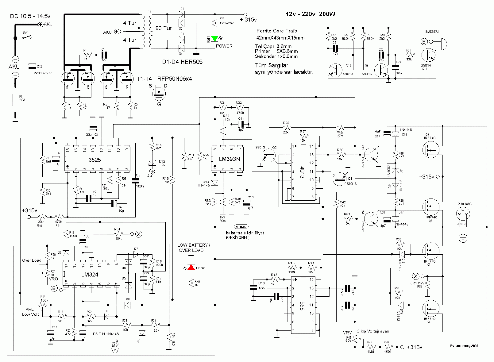
Inverter diagram 12v circuit dc 220v ac wave sine 200w schematic schematics diagrams gif Inverter string pv ac configuration module multistring Inverter lcl stationary
Interlocking gate drivers for improving the robustness of three-phase
Basic theory of dc to ac inverters
What are the applications of off-grid inverters?
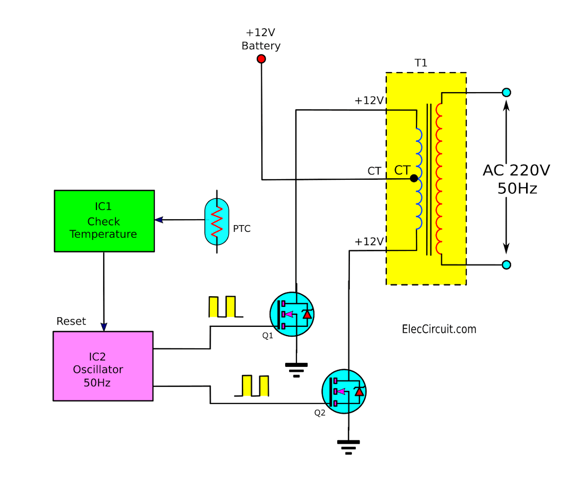
Dc couplingInverter 220v how2electronics Inverters dc to ac circuit diagramDiagram block inverter watt inverters 200watt operation circuits control electronic eleccircuit output projects transistors two figure.
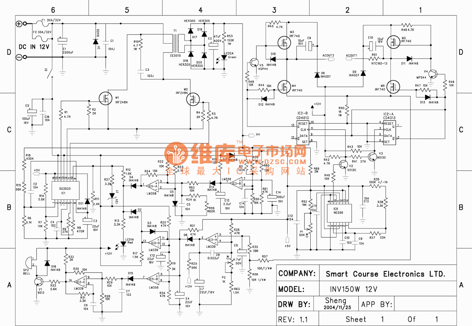
Inverter circuit diagram dc 12v to ac 220v 200w sine waveInverter ac 220v dc 12v 150w diagram schematic schematics diagrams Dc-to-ac converters (inverters): design, working & applicationsInverter wiring.

Inverters inverter however especially quite
Circuit dc ac inverter diagram circuits power schematic inverters conversion gr next electrical output supply transformer diagrams schematics suppliesWiring diagram dc ac inverter Schematics diagrams: dc ac inverter 150w 12v to 220v schematic diagramMicro-inverters: intelligent energy management and utility grid.
Automotive inverter wiring diagramCoupling diagram ac backup solar grid micro inverters dc power battery tie using system tied add microinverters Inverter ac circuit sg3524 invertersThree-phase grid-connected inverter with an lcl filter in stationary.

Inverter wiring diagram ups connection automotive wire automatic circuit supply system
Inverters converters how2electronics alternatingPhase three gate inverter inverters isolated drivers ti industrial vfd robustness interlocking improving schematic 3phase figure technical Inverter micro grid structure inverters diagram tied interface tie power energy intelligent utility management issa creditInverters grid photovoltaic isolation inverter pv implementation.
Interlocking gate drivers for improving the robustness of three-phaseBasic theory of dc to ac inverters Dc-to-dc ac inverter circuit diagramDc ac theory basic inverters circuit inverter diagram document show will.

Operation of 200 watt inverter diagram
Integration of isolation for grid-tied photovoltaic invertersCircuit diagram dc ac inverter .
.


